旋轉邊界框上的變換
本示例說明如何定義和使用旋轉邊界框。
注意
TorchVision 0.23 中釋出了對旋轉邊界框的支援,目前仍處於 BETA 階段。我們預計 API 不會更改,但可能存在一些罕見的邊緣情況。如果您發現任何問題,請在我們的 bug 跟蹤器上報告:https://github.com/pytorch/vision/issues?q=is:open+is:issue
首先,一些設定程式碼
from PIL import Image
from pathlib import Path
import matplotlib.pyplot as plt


import torch
from torchvision.tv_tensors import BoundingBoxes
from torchvision.transforms import v2
from helpers import plot

plt.rcParams["figure.figsize"] = [10, 5]
plt.rcParams["savefig.bbox"] = "tight"

# if you change the seed, make sure that the randomly-applied transforms
# properly show that the image can be both transformed and *not* transformed!
torch.manual_seed(0)

# If you're trying to run that on Colab, you can download the assets and the
# helpers from https://github.com/pytorch/vision/tree/main/gallery/
orig_img = Image.open(Path('../assets') / 'leaning_tower.jpg')
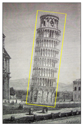
建立旋轉邊界框
透過例項化 BoundingBoxes 類來建立旋轉邊界框。建構函式的 format 引數決定邊界框是否為旋轉的。在此例項中,我們使用 CXCYWHR BoundingBoxFormat。前兩個值是邊界框中心的 X 和 Y 座標。接下來的兩個值是邊界框的寬度和高度,最後一個值是邊界框的旋轉角度(以度為單位)。
orig_box = BoundingBoxes(
    [
        [860.0, 1100, 570, 1840, -7],
    ],
    format="CXCYWHR",
    canvas_size=(orig_img.size[1], orig_img.size[0]),
)

plot([(orig_img, orig_box)], bbox_width=10)
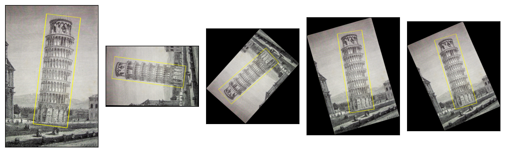
變換說明
rotater = v2.RandomRotation(degrees=(0, 180), expand=True)
rotated_imgs = [rotater((orig_img, orig_box)) for _ in range(4)]
plot([(orig_img, orig_box)] + rotated_imgs, bbox_width=10)
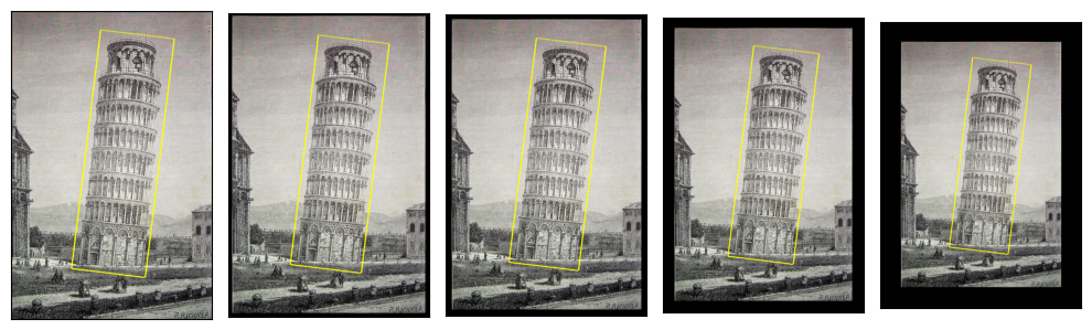
使用 Pad
padded_imgs_and_boxes = [
    v2.Pad(padding=padding)(orig_img, orig_box)
    for padding in (30, 50, 100, 200)
]
plot([(orig_img, orig_box)] + padded_imgs_and_boxes, bbox_width=10)
使用 Resize
resized_imgs = [
    v2.Resize(size=size)(orig_img, orig_box)
    for size in (30, 50, 100, orig_img.size)
]
plot([(orig_img, orig_box)] + resized_imgs, bbox_width=5)
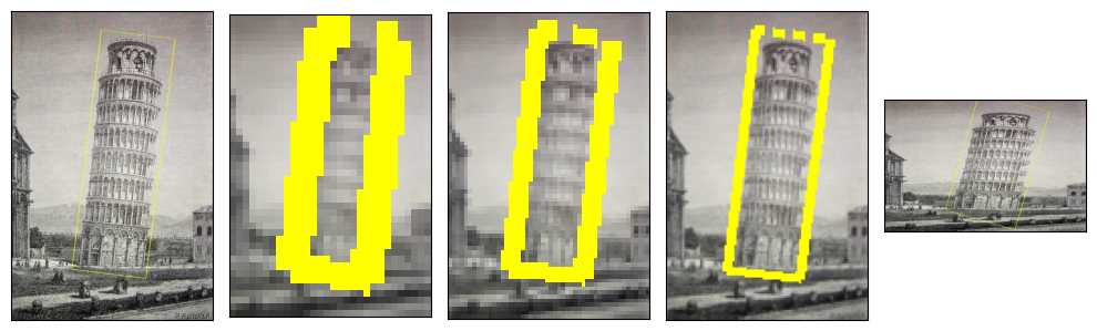
請注意,在畫素較少的影像中看起來更大的邊界框是一種偽影,而非真實情況。那僅僅是邊界框邊界的柵格化表示,由於我們指定了該柵格線的固定寬度,因此顯得更大。例如,當影像只有 30 畫素寬時,3 畫素寬的線相對較大。
裁剪模式及其對變換的影響
某些變換,例如 CenterCrop,可能導致變換後的邊界框部分超出變換後的(裁剪的)影像。通常,這可能發生在大多數 幾何變換 上。
在這種情況下,邊界框會根據其 clamping_mode 屬性裁剪到變換後的影像大小。 clamping_mode 有三種值,決定了變換後邊界框的裁剪方式。
None:不應用裁剪,邊界框可能部分超出影像。“hard”:邊界框被裁剪到影像大小,使其所有角點都位於影像畫布內。這可能會導致資訊丟失,並可能導致不直觀的結果。但對於某些應用程式可能是必需的,例如,如果模型不支援影像外部的邊界框。
“soft”:這是
None和“hard”之間的一種中間模式:邊界框被裁剪,但不如“hard”模式嚴格。某些邊界框尺寸可能仍超出影像。這是構造BoundingBoxes時的預設值。
注意
對於軸對齊邊界框,“soft” 和 “hard” 模式的行為相同,因為邊界框始終被裁剪到影像大小。
讓我們用 CenterCrop 變換來說明裁剪模式。
assert orig_box.clamping_mode == "soft"

box_hard_clamping = BoundingBoxes(orig_box, format=orig_box.format, canvas_size=orig_box.canvas_size, clamping_mode="hard")

box_no_clamping = BoundingBoxes(orig_box, format=orig_box.format, canvas_size=orig_box.canvas_size, clamping_mode=None)

crop_sizes = (800, 1200, 2000, orig_img.size)
soft_center_crops_and_boxes = [
    v2.CenterCrop(size=size)(orig_img, orig_box)
    for size in crop_sizes
]

hard_center_crops_and_boxes = [
    v2.CenterCrop(size=size)(orig_img, box_hard_clamping)
    for size in crop_sizes
]

no_clamping_center_crops_and_boxes = [
    v2.CenterCrop(size=size)(orig_img, box_no_clamping)
    for size in crop_sizes
]

plot([[(orig_img, box_hard_clamping)] + hard_center_crops_and_boxes,
      [(orig_img, orig_box)] + soft_center_crops_and_boxes,
      [(orig_img, box_no_clamping)] + no_clamping_center_crops_and_boxes],
     bbox_width=10)
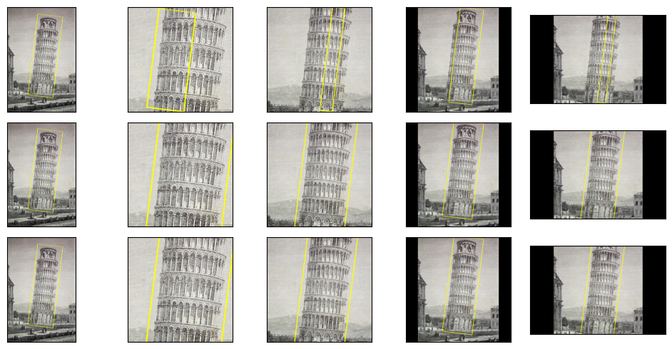
上面的圖顯示了“hard”裁剪模式、“soft”模式和 None 模式,順序依次是。雖然“soft”和 None 模式的結果圖相似,但它們不會產生完全相同的裁剪邊界框。未裁剪的邊界框將顯示尺寸偏離影像的情況。
print("boxes with soft clamping:")
print(soft_center_crops_and_boxes)
print()
print("boxes with no clamping:")
print(no_clamping_center_crops_and_boxes)
boxes with soft clamping:
[(<PIL.Image.Image image mode=RGB size=800x800 at 0x7F7F333DA6B0>, BoundingBoxes([[478.8188, 400.9185, 570.0000, 874.1443,  -7.0000]], format=BoundingBoxFormat.CXCYWHR, canvas_size=(800, 800), clamping_mode=soft)), (<PIL.Image.Image image mode=RGB size=1200x1200 at 0x7F7F333DA770>, BoundingBoxes([[ 678.9319,  600.0001,  569.9992, 1278.9989,   -7.0000]], format=BoundingBoxFormat.CXCYWHR, canvas_size=(1200, 1200), clamping_mode=soft)), (<PIL.Image.Image image mode=RGB size=2000x2000 at 0x7F7F333DA860>, BoundingBoxes([[1089.0000,  918.0000,  570.0001, 1840.0000,   -7.0000]], format=BoundingBoxFormat.CXCYWHR, canvas_size=(2000, 2000), clamping_mode=soft)), (<PIL.Image.Image image mode=RGB size=2364x1542 at 0x7F7F333DA920>, BoundingBoxes([[1260.9314,  771.0001,  570.0002, 1623.5675,   -7.0000]], format=BoundingBoxFormat.CXCYWHR, canvas_size=(1542, 2364), clamping_mode=soft))]

boxes with no clamping:
[(<PIL.Image.Image image mode=RGB size=800x800 at 0x7F7F333DA350>, BoundingBoxes([[ 489.,  318.,  570., 1840.,   -7.]], format=BoundingBoxFormat.CXCYWHR, canvas_size=(800, 800), clamping_mode=None)), (<PIL.Image.Image image mode=RGB size=1200x1200 at 0x7F7F333DA290>, BoundingBoxes([[ 689.,  518.,  570., 1840.,   -7.]], format=BoundingBoxFormat.CXCYWHR, canvas_size=(1200, 1200), clamping_mode=None)), (<PIL.Image.Image image mode=RGB size=2000x2000 at 0x7F7F333DA1A0>, BoundingBoxes([[1089.,  918.,  570., 1840.,   -7.]], format=BoundingBoxFormat.CXCYWHR, canvas_size=(2000, 2000), clamping_mode=None)), (<PIL.Image.Image image mode=RGB size=2364x1542 at 0x7F7F333DA0E0>, BoundingBoxes([[1271.,  689.,  570., 1840.,   -7.]], format=BoundingBoxFormat.CXCYWHR, canvas_size=(1542, 2364), clamping_mode=None))]
設定裁剪模式
決定應用於邊界框的裁剪策略的 clamping_mode 屬性可以透過多種方式設定:
在使用其
BoundingBoxes建構函式建立邊界框時,如上面的示例所示。透過直接在現有例項上設定該屬性,例如
boxes.clamping_mode = "hard"。透過呼叫
SetClampingMode變換。
另外,請記住,您始終可以透過呼叫 ClampBoundingBoxes() 變換來手動裁剪邊界框!這是一個說明所有這些選項的示例。
t = v2.Compose([
    v2.CenterCrop(size=(800,)),  # clamps according to the current clamping_mode
                                 # attribute, in this case set by the constructor
    v2.SetClampingMode(None),  # sets the clamping_mode attribute for future transforms
    v2.Pad(padding=3),  # clamps according to the current clamping_mode
                        # i.e. ``None``
    v2.ClampBoundingBoxes(clamping_mode="soft"),  # clamps with "soft" mode.
])

out_img, out_box = t(orig_img, orig_box)
plot([(orig_img, orig_box), (out_img, out_box)], bbox_width=10)

指令碼總執行時間: (0 分鐘 6.887 秒)
